
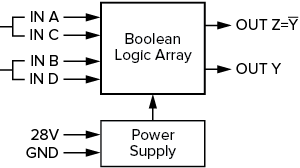
The NEXSYS Defined Logic device consist of four configuration types of a Series C (8 pin) component. The two input / four output devices performs the Boolean logic gate operations AND, NAND, OR, NOR, EXOR, EXNOR, as well as BUFFER and NOT (Inverter).
28V: Operating Voltage (nom.), 4 mA current draw (max.).
GND: Continuous Ground required.
A, B, C, D: Digital electronic inputs that detect logic level signals (1 or 0). Inputs will sense signal levels that are present upon power-up. Options include specifying inputs A and C as either Pull-up or Pull-down to define the signal sense levels of a floating input state. For the DL1 variant only, inputs A and C are specified identically (Pull-up or Pull-down) since they are wired together externally. Inputs B and D are factory configured and fixed as Pull-ups.
Y, Z: Active outputs are either High Impedance or Ground based on the configured logic gate(s). Outputs Y and Z are orthogonal in DL1, DL3, and DL4 configurations, and are independent for the DL2 configuration. Output load capacity is 2.0 A (Resistive).
The Defined Logic 1 is a component that offers a decode of two (tied) pairs of four inputs to control two orthogonal outputs to perform as an EXOR or EXNOR logic gate which detects when one signal is active but not both.
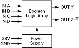
The Defined Logic 2 is a component that offers a decode of two independent logic gates, and each includes two inputs that each control one dedicated output.

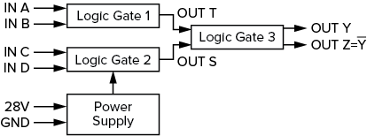
The Defined Logic 3 is a component that offers a decode of two independent logic gates that cascade into a third gate to control two orthogonal outputs.
The Defined Logic 4 is a component that acts as a 4 bit binary encoder for up to four inputs controlling two orthogonal outputs.
To help system designers understand the potential of NEXSYS Component Technology, we have assembled a collection of Application Notes. The links below show example applications that utilize the Defined Logic component.
Power Converter Status
 This application depicts a power converter indicator with ON/OFF, fault, and overheat status indicators that senses power signals from an external mechanical relay to determine the ON and OFF indication states. Discrete signals from the converter are used to indicate fault conditions.
