
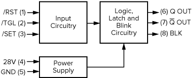
The NEXSYS Electronic Latch (EL1, EL2) is a Series C (8 pin) electronic circuit with multiple trigger modes that activate orthogonal (flip-flop) switching between two known states.
28V: Operating voltage (nom.), 4 mA current draw (max.).
GND: Continuous ground required.
/RST: immediate activation to reset (/RST) state.
/TGL: Detects signal transitions, which function as the control interface to drive outputs.
/SET: immediate activation to set (/SET) state.
Q, Q: Open-drain outputs are Ground when active and High Impedance when not active. Power-up state (see Configuration Options) determines initial state of outputs and blink (BLK). The output load capacity is 2.0 A (Resistive).
BLK: Open-drain output that produces a 1 Hz square wave (50% duty cycle) signal when active and is High Impedance when not active.
The NEXSYS Electronic Latch is available in two options based on desired power-up state with no inputs active.
Electronic Latch 1 (EL1): Powers up with Q output at High Impedance, Q at Ground and BLK inactive (High Impedance).
Electronic Latch 2 (EL2): Powers up with Q output at Ground, Q at High Impedance and BLK active (oscillating).
To help system designers understand the potential of NEXSYS Component Technology, we have assembled a collection of Application Notes. The links below show example applications that utilize the Electronic Latch component.
