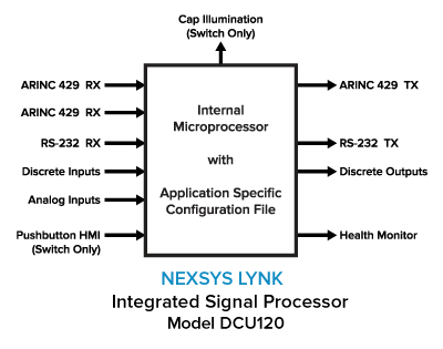
The DCU120 is a highly configurable Integrated Signal Processor (ISP) based on a wide range of inputs and outputs and an application-specific Configuration File (CF).
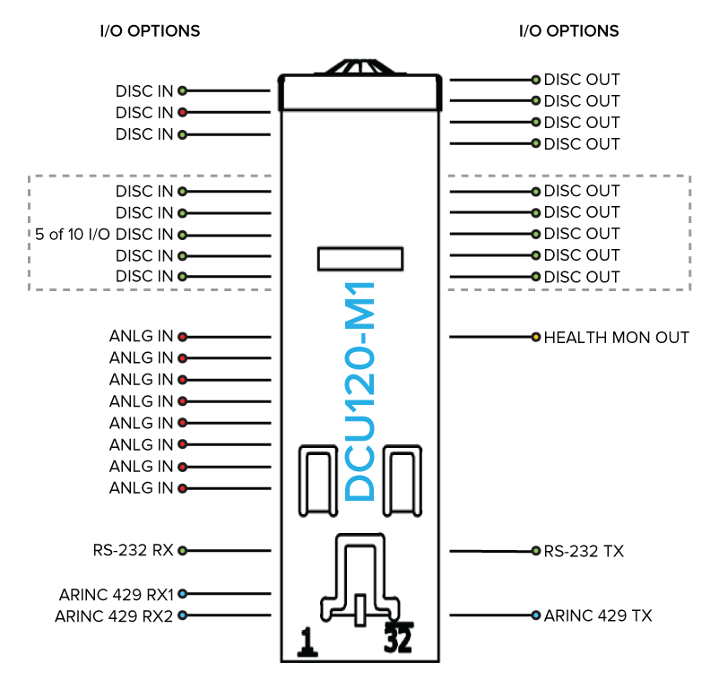
The DCU120 includes the following Inputs/Outputs (I/O) common to all form factors: 1) ARINC 429 Transceiver (2 Bus In / 1 Bus Out), 2) RS232 Transceiver, 3) Discrete Input and Outputs, 4) Analog Inputs, and 5) an internal health monitor output. The number of Discrete Inputs and Outputs varies by form factor and configuration specifics.
Additionally, the DCU120-S can be configured to provide HMI by specifying a momentary action switch (acts as an additional Discrete Input to the microprocessor) and an illuminated cap that provides visual feedback to the operator. Momentary switch can be programmed to act as an alternate action switch.
The Configuration File is what defines the relationship between the inputs and the outputs. Each Configuration File development begins with a detailed capture of specific customer requirements. In addition to processing, specific operations that can be included in the CF Include:
Application engineers at AAI work closely with avionics designers to make the CF development process efficient and comprehensive.
Configuration Files are tested internally using a proprietary simulator to provide logic verification and ensure that customer requirements are being accomplished. Working in a simulated environment reduces valuable design time.
Upon finalization and customer approval, the Configuration File is released for production, factory loaded onto the DCU, and tested against the specific customer requirements.
The Configuration File is not field loadable or operator configurable, nor does it contain any user-modifiable code.
The small form-factor of the DCU120, combined with the infinite combinations of signal processing available, creates a powerful solution to avionics signal processing challenges.
Discrete Inputs
An event can be triggered by one or more discrete inputs changing state (rising edge or falling edge). The number of discrete inputs varies by form factor. Additional discrete inputs can be incorporated by using the analog inputs as discrete inputs. Discrete inputs will be internally debounced. In the DCU120-S, the inclusion of an internal momentary switch can provide an additional discrete input via human-machine interface. Momentary switch can be programmed to act as an alternate action switch.
Analog Inputs
Analog Inputs can accept input voltages from -11 VDC to +32 VDC. For each analog input, one or more “voltage thresholds” can be established and an event can be triggered by the sense voltage crossing (rising or falling) a voltage threshold. For increased resolution at low voltage readings, a tighter analog input range is available and analog inputs can be paired to use a different analog input as its ground reference to address situations where the sense ground reference is different from general aircraft ground or unit ground. Analog inputs will be internally debounced. Analog inputs can also be used as additional discrete inputs.
ARINC 429 RX/TX
Each DCU120 has the ability to receive multiple labels on two separate ARINC 429 data bus inputs and transmit multiple labels on one ARINC 429 data bus output. Each data bus is separably configurable for high or low speed. Events can be triggered by ARINC data received and outbound ARINC messages can be triggered at the completion of an event. Communication between ISP units can be accomplished using an ARINC 429 data connection between units.
RS232 RX/TX
Each ISP includes an RS232 transceiver that is configurable for parity, stop bits, start bits, message length, and baud rate. Maximum message length is 25 ASCII bytes, terminated by the one or two characters defined in the configuration file. Events can be triggered by RS232 data received, and outbound RS232 messages can be triggered at the completion of an event.
Discrete Outputs
A discrete output can be specified as either open (high impedance) or ground and is capable of sinking up to 0.25 A. In the DCU120-S, each illuminated segment of the cap will be linked to a dedicated discrete output that can be connected to an additional indicator or external avionics systems.
Health Monitor
The health monitor output is a normally ground output that will become open (high impedance) if the processor stops operating or the unit loses power. When the health monitor is open (fail), all outputs from the ISP are disabled.
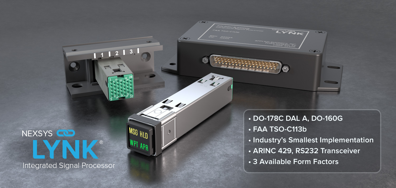
Form Factors
The Integrated Signal Processor can be packaged inside one of three familiar form factors from Applied Avionics. The primary difference between the form factors is the number of I/O required and the desire for an integrated illuminated cap with optional pushbutton Human Machine Interface (HMI).
| VIVISUN Switch/Indicator (DCU120-S) |
NEXSYS Module (DCU120-M1) |
NEXSYS Box (DCU120-B) |
|
| Application Specific Configuration File | ✓ | ✓ | ✓ |
| ARINC 429 RX/TX | ✓ | ✓ | ✓ |
| RS-232 RX/TX | ✓ | ✓ | ✓ |
| Inputs | Up to 16 (incl. 8 Analog) |
Up to 16 (incl. 8 Analog) |
31 (incl. 8 Analog) |
| Outputs | Up to 9 | Up to 9 | 17 |
| Health Output | ✓ | ✓ | ✓ |
| Internal Illuminated Cap Connections | ✓ | n/a | n/a |
| Pushbutton HMI | ✓ | n/a | n/a |
| Pinout Max | 32 (Solderless Conn. Plug) |
32 (Solderless Conn. Plug) |
62 (D-sub) |
| Weight | 50 g (0.11 lb) | 35 g (0.08 lb) | 270 g (0.60 lb) |
| Dimensions | 0.75” x 0.75” x 3.54” | 0.85” x 0.795” x 2.24” | 1.16” x 2.70” x 5.76” |
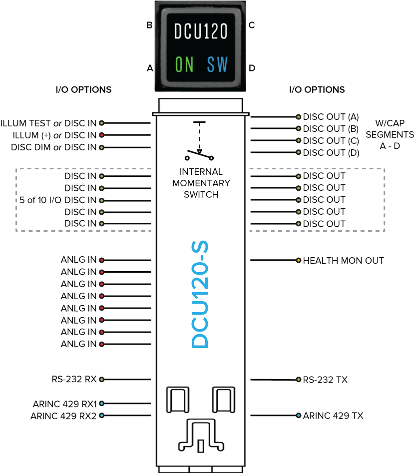
The DCU120-S fits in a standard square panel cutout for a VIVISUN advanced illuminated pushbutton switch. The DCU120-S can be designed with an internal momentary action switch that provides human input (pressing the switch cap) directly to the microcontroller. Momentary switch can be programmed to act as an alternate action switch.
The DCU120-S also has the ability to illuminate the cap segments (1, 2, 3 or 4 segments) internally without any additional external wiring, eliminating the need for separate illumination wires. The DCU120-S can support a full range of cap options for internal and external illumination test and dimming control.
To take maximum advantage of the 32 pin solderless connector, five external pins can be used as discrete inputs or discrete outputs as specified at the time of order. Depending on the specific application, a DCU120-S can have up to 16 discrete inputs (including 8 with analog capability) and up to 9 discrete outputs. The solderless connector plug accepts 22 to 28 gauge crimped wire connections.
The DCU120-M1 can be rail, bracket or harness mounted. Similar to the DCU120-S, five external pins can be used as discrete inputs or discrete outputs as specified at the time of order.
Depending on the specific application, a DCU120-M1 can have up to 16 discrete inputs (including 8 with analog capability) and up to 9 discrete outputs. The 32 pin solderless connector plug accepts 22 to 28 gauge crimped wire connections.
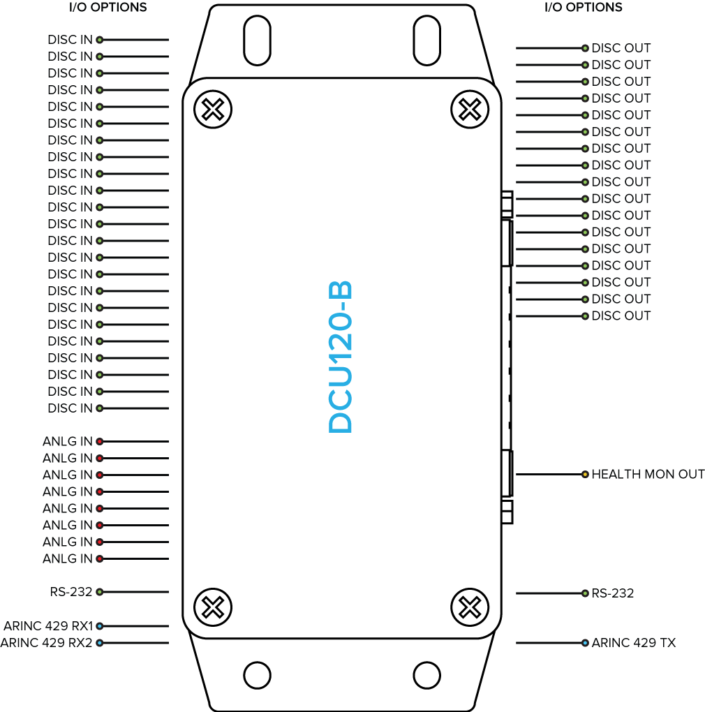
The DCU120-B is designed for fixed mounting, and has the highest input/output capacity of any of the ISP form factors. Each external pin has a single function, and a DCU120-B can have a total of 31 discrete inputs (including 8 with analog capability) and 17 discrete outputs. A standard 62 pin D-sub connector makes harness interface simple.
Applications for the DCU120-B include smoke detection systems with multiple inputs or as an output expander for limited output avionics systems.