
The NEXSYS Electronic Rotary (ER1) is a Series C (8 pin) electronic rotary controller that provides incremental cycling through a loop of four latched output states. The increment signal can come from successive switch closures or from a remote source.
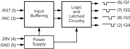
28V: Operating voltage (nom.), 4 mA current draw (max.).
GND: Continuous ground required.
/INC: Detects signal transitions, which function as the control interface to loop through four outputs.
/RST: immediate activation to reset (/RST) state. /INC input has no effect when /RST is held low.
/Q1, /Q2, /Q3, /Q4: Open drain outputs are High Impedance becoming Ground when output is active. Only one output is active at a time. The output load capacity is 2.0 A (Resistive).
The Electronic Rotary powers-up in a known state (Q1 Active). Following power-up, the /INC input will detect a signal transition, and successive transitions will activate the next sequence in a loop of four latched outputs. The number of latched outputs are reduced by wiring the next output state back to /RST (i.e., wiring Q4 to /RST creates a three-state rotary device).
To help system designers understand the potential of NEXSYS Component Technology, we have assembled a collection of Application Notes. The links below show example applications that utilize the Electronic Rotary component.
