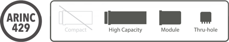
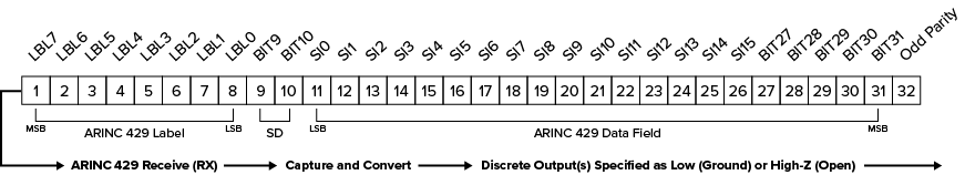
The NEXSYS ARINC 429 Signal Converter is a Series N (8 pin) or Series R (12 pin) autonomous ARINC 429 receiver that includes the protocol logic necessary to capture and convert a 32-bit ARINC 429 data word into a discrete output. The unit can also assist with encoding applications by performing a multi-bit decode operation.
The NEXSYS Signal Converter is available in three configuration types: Single-Bit Converter (SR429/1M), Multi-Bit Converter (SR429/4M), and Multi-Bit Decoding Converter (SR429/4D) based on the requirements for data conversion and output control.
The NEXSYS ARINC 429 Signal Converter offers a more efficient design than larger adapter boxes, which introduce significantly more cost and complexity than is practical for straightforward applications. The simple input-pin interface does not rely on any microcontroller software or firmware control, eliminating qualification requirements to DO-178 or DO-254.
28V: Operating voltage (nom.), 8 mA current draw (max.)
GND: Continuous Ground required.
RXA, RXB: Receive (RX) ARINC 429 unit of transmission (TX). Signal Converters have options for specifying the label (000-377), the bit or multiple bits to be used for driving active outputs (see below), enabling/disabling SDI bits (9, 10) for valid data source identification, and specifying high or low-speed transmission.
The three NEXSYS Signal Converter configuration types (SR429/1M, SR429/4M, and SR429/4D) provide up to three distinct output control activation options; Discrete Outputs, Decoded Outputs and the Failure Output (see below).
All outputs are open-drain (High Impedance) when not active. The output load capacity is 1.0 A (Resistive) for the SR429/1M and 0.5 A (Resistive) for SR429/4M and SR429/4D.
Discrete Outputs - Active outputs are converted from one or more of the actual bits in the ARINC 429 data word. Converted single bits (SR429/1M) and multiple bits (SR429/4M) can be active outputs and are specified as High Impedance when data bit = 1 (Standard) or Ground when data bit = 1 (Inverted). When data bit = 0, the output is orthogonal to the specified level when data bit = 1.
Decoded Outputs - Active outputs can also represent the decoding of multiple bits. Options for Decoded Outputs include the decoding of two or three data bits (SR429/4D) and the decoding of the Sign/Status Matrix bits (30, 31) available in the SR429/4M. Active Decoded Outputs can be specified as Ground or High Impedance when the decoded condition equals TRUE.
Failure Output - The internal IC health can be monitored and produce an active output upon failure of the receiver IC and/or failure to receive valid ARINC data within a specified time buffer (0.5 – 15 sec.). This option also monitors loss of power. The Failure Output becomes active upon failure of the receiver IC and can be specified as either:
Fail = High Impedance (Health), Normal = Ground
Fail = Ground (Watchdog), Normal = High Impedance
In the SR429/1M Signal Converter, only the Health version of the Failure Output is available which can be enhanced by combining additional external failure warnings into one active output.
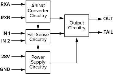
The SR429/1M Single-Bit Converter is a Series N (8 pin) device that offers one Discrete Output (OUT) from a single label and bit and one output (FAIL) that activates when the Fail Sense Circuitry detects a failure condition.
The Fail Sense Circuitry drives the FAIL output and can optionally combine the internal Failure Output signal (Health) from the IC with up to two external sources. IN 1 and IN 2 are inputs to the Fail Sense Circuitry with predefined failure signal definitions. The FAIL output of the SR429/1M is defined as Fail = High Impedance and Normal = Ground. The Fail Sense Circuitry can be bypassed if unused.
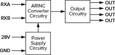
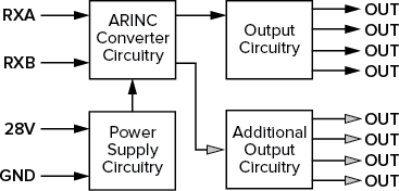
The SR249/4M features the ability to convert up to four different data bits into active Discrete Outputs. Additional options include a Decoded Output of the Sign/Status Matrix (SSM) bits 30 and 31 and inclusion of Failure Outputs.
Series N (8 pin) SR429/4M: Four primary outputs can be Discrete Outputs or Failure Outputs, active on four separate pins. These Discrete Outputs and Failure Outputs can also be repeated within the four available outputs to avoid external splicing.
Series R (12 pin) SR429/4M: In addition to the four primary outputs detailed above for the Series N SR429/4M, the Series R SR429/4M adds four additional outputs to the four primary outputs. Options for the four additional outputs include Discrete Outputs (inverted outputs based on the bits used in the primary outputs), Failure Outputs, or Decoded Outputs from decoding the Sign/Status Matrix (SSM) bits 30 and 31. The SSM binary decode 00 can be repurposed as a Discrete or Failure Output.
The SR249/4D features Decoded Outputs resulting from a multi-bit binary decode of two or three bits.
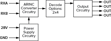
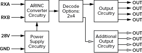
SR429/4D with 2x4 Decoder
Series N (8 pin) SR429/4D: The decoding of two bits (2X4) producing four Decoded Outputs. Binary decodes 00 and/or 11 can be repurposed as Discrete or Failure Outputs.
Series R (12 pin) SR429/4D: The decoding of two bits (2x4) producing four Decoded Outputs plus two Discrete Outputs based on decoded input and two unrelated Discrete or Failure Outputs for a total of eight outputs.
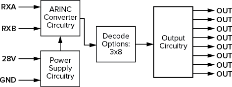
SR429/4D with 3x8 Decoder
Series R (12 pin) SR429/4D: The decoding of three bits (3x8) producing eight Decoded Outputs. Binary decodes 000 and/or 111 can be repurposed as Discrete or Failure Outputs.
To help system designers understand the potential of NEXSYS Component Technology, we have assembled a collection of Application Notes. The links below show example applications that utilize the ARINC 429 Signal Converter component.
Autopilot Status Indication
 This application depicts an autopilot system status indicator with a built-in Multi-Bit Converter. The converter reads the ARINC 429 data and decodes the selected label and bits. Each bit has a dedicated output which when active, illuminate indicators that correspond to the active status of the autopilot system.
