Step 1
Examine the pushbutton switch cap assuring the cap is in the unlatched position. Identify the two extraction slots positioned on either side of the pushbutton cap.
Step 2
Extract the switch cap by using the Cap Extractor Tool (Part Number: 17-150) or by applying finger pressure on two sides of the switch cap pulling the switch cap from the switch body.
Step 3
Remove switch cap from the switch body by gently removing the cap pins from the hinged slide retainer.
Step 4
Remove the locking sleeve by sliding the sleeve over the switch body from the back. Note: The optional spacer can also be removed by sliding it from the back of the switch body.
Step 5
Insert the back of the switch body into the panel cutout by sliding it through the panel from the front. Ensure the switch body label “TOP” is positioned up.
Step 6
From behind the mounting panel, replace the locking sleeve onto the switch body and sliding it forward against the mounting panel.
Step 7
From the front of the switch body locate the two slot head integral mounting screws in the base of the body. Tighten the two screws until the Integral Mounting Hardware pulls the mounting sleeve against the mounting panel. Recommended torque is 18-25 inch ounces.
Step 8
Replace the switch cap by inserting the cap pins into the slide retainer and push the cap into the switch body.
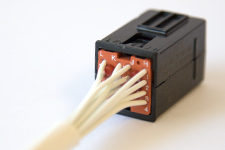
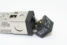
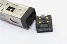
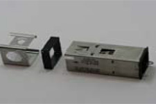
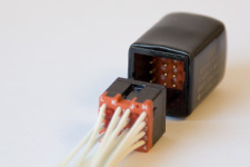
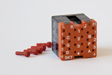
The NEXSYS Module accepts a similar solderless Quik-Connect connector plug. The module connector plug is Part Number 18-440 and accepts the (18-219, MIL-C-39029/22-192) crimp sockets. The NEXSYS Module has three primary mounting options :
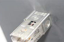
Option 1
Each Module is provided with a flame retardant vinyl boot for use when in-line installation is preferred. This option provides packaging flexibility as the module may be integrated in a position that best accommodates the existing packaging.
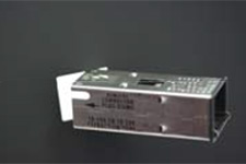
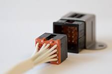
Option 2
When individual mounting is preferred, the Module may be mounted in either a right angle or a flush mount bracket. The bracket is permanently attached behind the control panel via fasteners or bonding compounds. Bracket mounting has the advantage of allowing each NEXSYS Module to be mounted separately in order to reduce wire runs and take advantage of preferred mounting points.
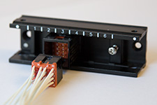
Option 3
When multiple NEXSYS Modules are used they may be mounted in a standard Type I, M81714/5-5 rail assembly. NEXSYS offers a rail that accepts up to 3 NEXSYS Modules and is an effective off-the-shelf option for effectively packaging multiple NEXSYS Modules.
Part Numbers: 18-200 Compact Body, 18-240 High Capacity Body, 18-440 Compact Body w/NEXSYS components, 18-442 High Capacity Body w/NEXSYS components and NEXSYS Module.
Recommended Tools and hardware – Wire Extractor/Insert Tool (Part Number: 18-216), Quik-Connect Plug Extraction Tool (Part Number: 18-234), Crimp Contact Sockets (Part Number 18-219, M39029/22-192). Tools and Hardware are available as a standard kit refer to Accessories under Product Features or the Part Configurator.
Step 1
For pinout detail refer to Product Features. Unused pinout positions should be filled with red 18-215 sealing plugs.
Step 2
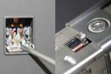
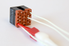
Wires with the MIL-C-39029/22-192 sockets are inserted into the back of the plug by use of a Wire Extractor/Insert Tool (P/N 18-216 or M81969/14-10).
Step 3
Plug into switch or module housing.
Mating the QUIK-CONNECT Plug to the switch housing does not require tools. However, an extraction tool (Part Number 18-234) is required for plug removal.
Note: 12 Sealing plugs (Part Number 18-215) are provided with each plug for the unused wire positions.