- Home
- Technical Resources
- Application Notes
- APX-064
Dual Transponder Control and Monitoring
 Click to Zoom
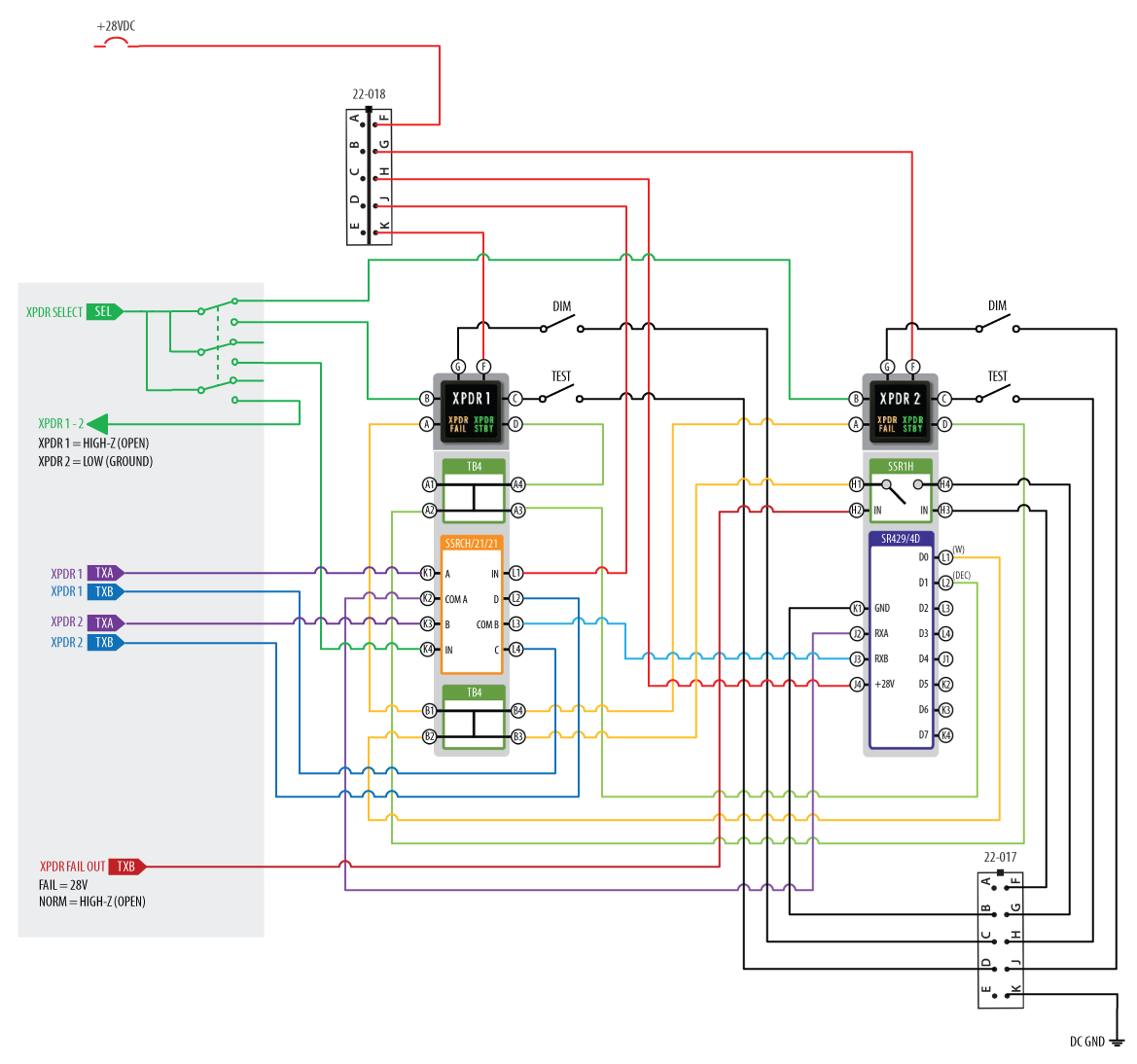
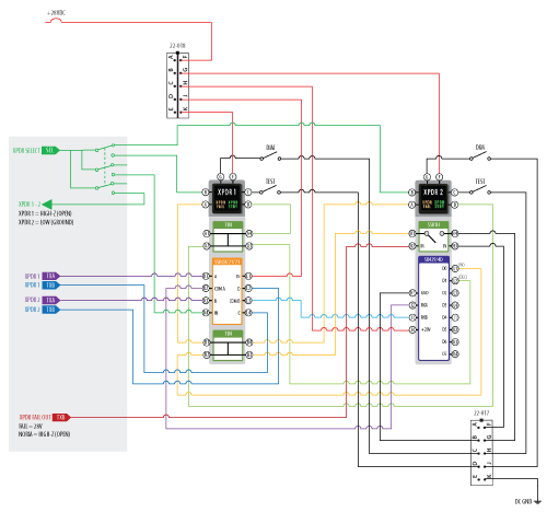
Dual transponder control and transponder monitoring via an ARINC 429 data bus is a common aircraft installation. Annunciators are used to report dual transponder status and an ARINC 429 decoder is typically used to provide discrete outputs to illuminate annunciators and advise of transponder status.
This functionality can be accomplished with VIVISUN annunciators configured with an internal NEXSYS ARINC 429 Multi-bit Decoding Converter (SR429/4D). The SR429/4D can decode and convert up to three different bits from a single label and provide a discrete output. The image depicts a typical dual transponder application that uses VIVISUN annunciators with NEXSYS components.
This application includes a NEXSYS normally open (NO) Solid State Relay (SSR1H) which functions as an inverter on XPDR failure. The Combination Solid State Relay (SSRC) functions to switch ARINC 429 data upon XPDR switch transition. The design also includes internal terminal blocks to bus the annunciator signals and failure detection that monitors for failure of the internal IC, failure to receive valid ARINC data within a specified time buffer and loss of unit power.
Application Truth Statements:
- SR429/4D functions to receive (RX), decode and convert the specified ARINC 429 data word.
- 1.1 D1 Output (L2) is 0, Low (Ground) when Decode = TRUE, else D1 is 1, High-Z (Open).
- 1.2 XPDR STBY indicators are energized when Decode = TRUE, else NOT energized.
- 1.3 D0 Output (L1) is 0, Low (Ground) when Watchdog = FAIL, else D0 is 1, High-Z (Open).
- 1.4 XPDR FAIL indicators are energized when Watchdog = FAIL, else NOT energized (Watchdog).
- SSR1H functions as a signal inverter upon XPDR equipment failure.
- 2.1 XPDR FAIL indicators are energized when XPDR FAIL OUT = FAIL, else NOT energized (XPDR FAIL).
- SSRCH functions to switch ARINC 429 upon XPDR SEL switch transition.
- 3.1 XPDR 1 is Active when XPDR SEL is 1, High-Z (Open), else XPDR 2 is Active.
- 3.2 XPDR 1 indicator is energized when XPDR SEL is 1, High-Z (Open), else NOT energized.
- 3.3 XPDR 2 is Active when XPDR SEL is 0, Low (Ground), else XPDR 1 is Active.
- 3.4 XPDR 2 indicator is energized when XPDR SEL is 0, Low (Ground), else NOT energized.
Disclaimer: The configurations and diagrams shown above are provided by Applied Avionics, Inc. as a general example only. The recipient is solely responsible for actual design, electrical wiring, validation, testing, applicability and functionality of the product in regards to the customer’s specific application.